KF5N Radio Experimentation Site
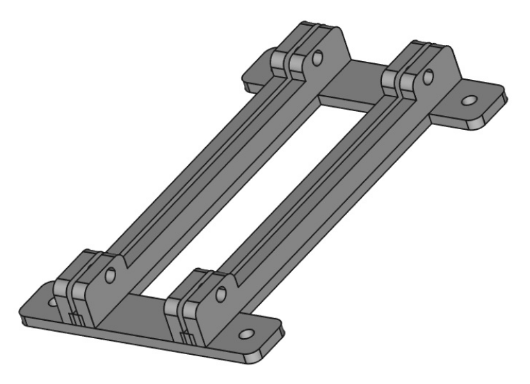
Dual Bracket
Dual Bracket for T41 Modules
This is a Freecad file design of a dual bracket for the T41 Software Defined Transceiver. This bracket was designed to hold a QSD and a QSE module, however, it could be used to combine other modules to create a “super module”.
Freecad can be downloaded here:
An STL file is included in the repository in addition to the Freecad design file. The repository is here:
https://github.com/Greg-R/bracket_dual_T41
A “Super Module” with QSD2 QSE2 and Si5351
The dual bracket is intended to allow a special combination of the QSE, QSD, and Si5351 modules. More specifically, the QSD2 and QSE2 modules which need a very short path from the Si5351 outputs to the divide-by-two quadrature generator circuits onboard the QSD2 and QSE2. These digital circuits need nice sharp waveforms, and the shunt capacitance should be kept to a bare minimum. The Si5351 outputs square waves, however, the drive power available is minimal, thus the necessity to keep loading as low as possible.
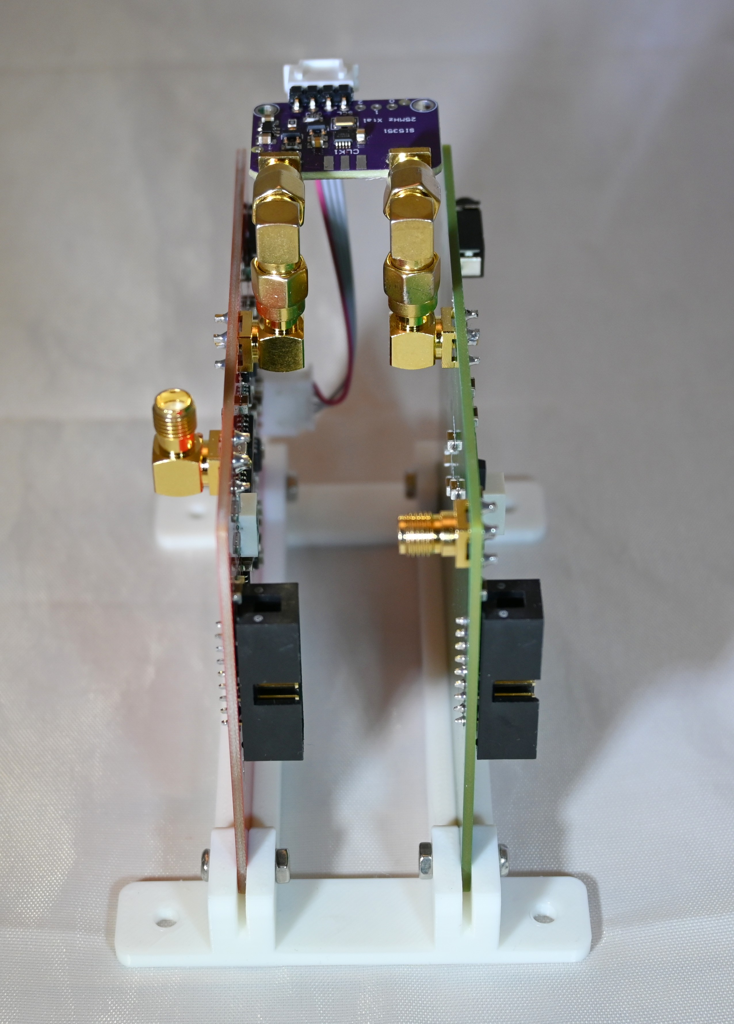
A picture is worth a thousand words, so here are four photos of the super-module:
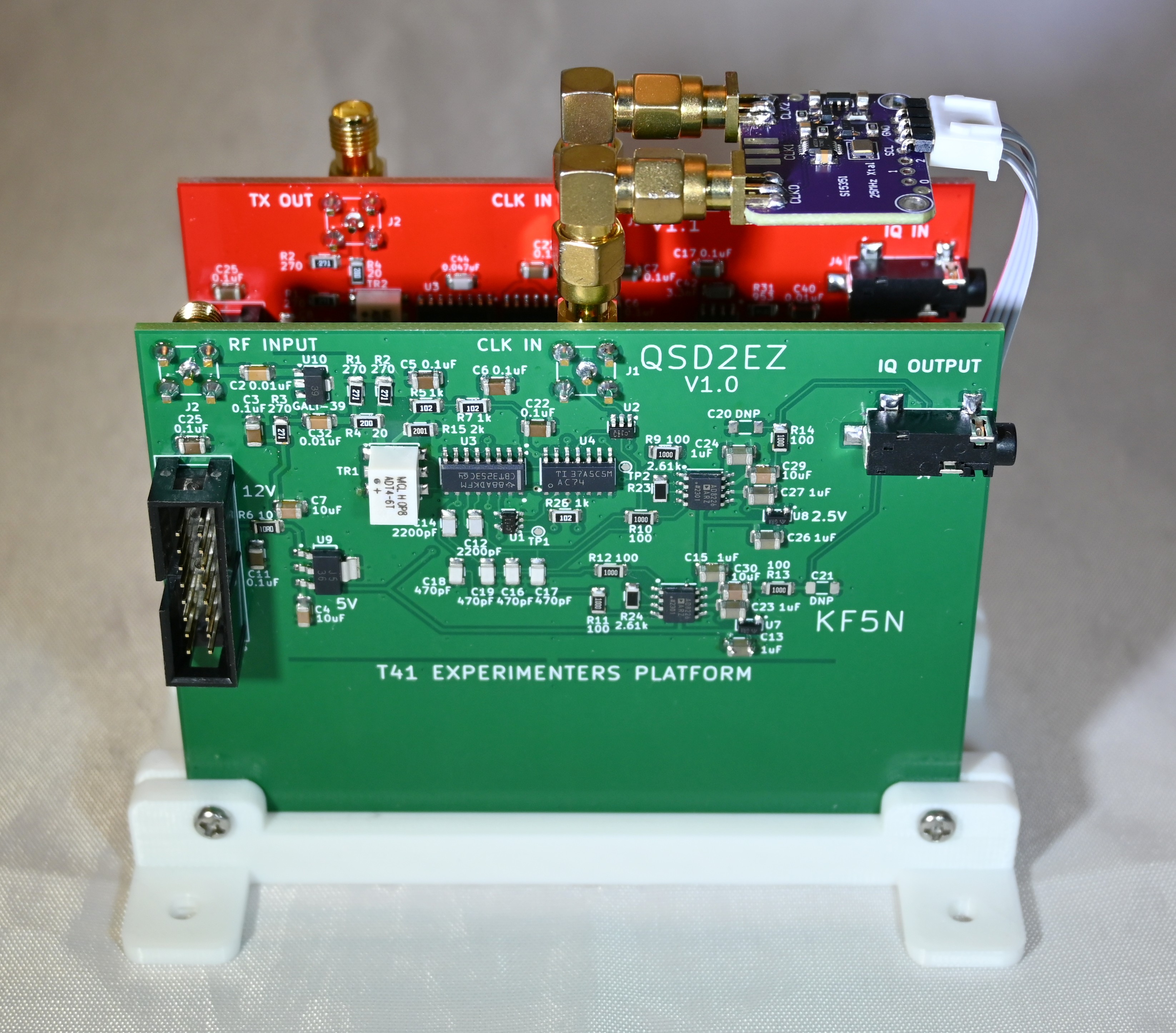
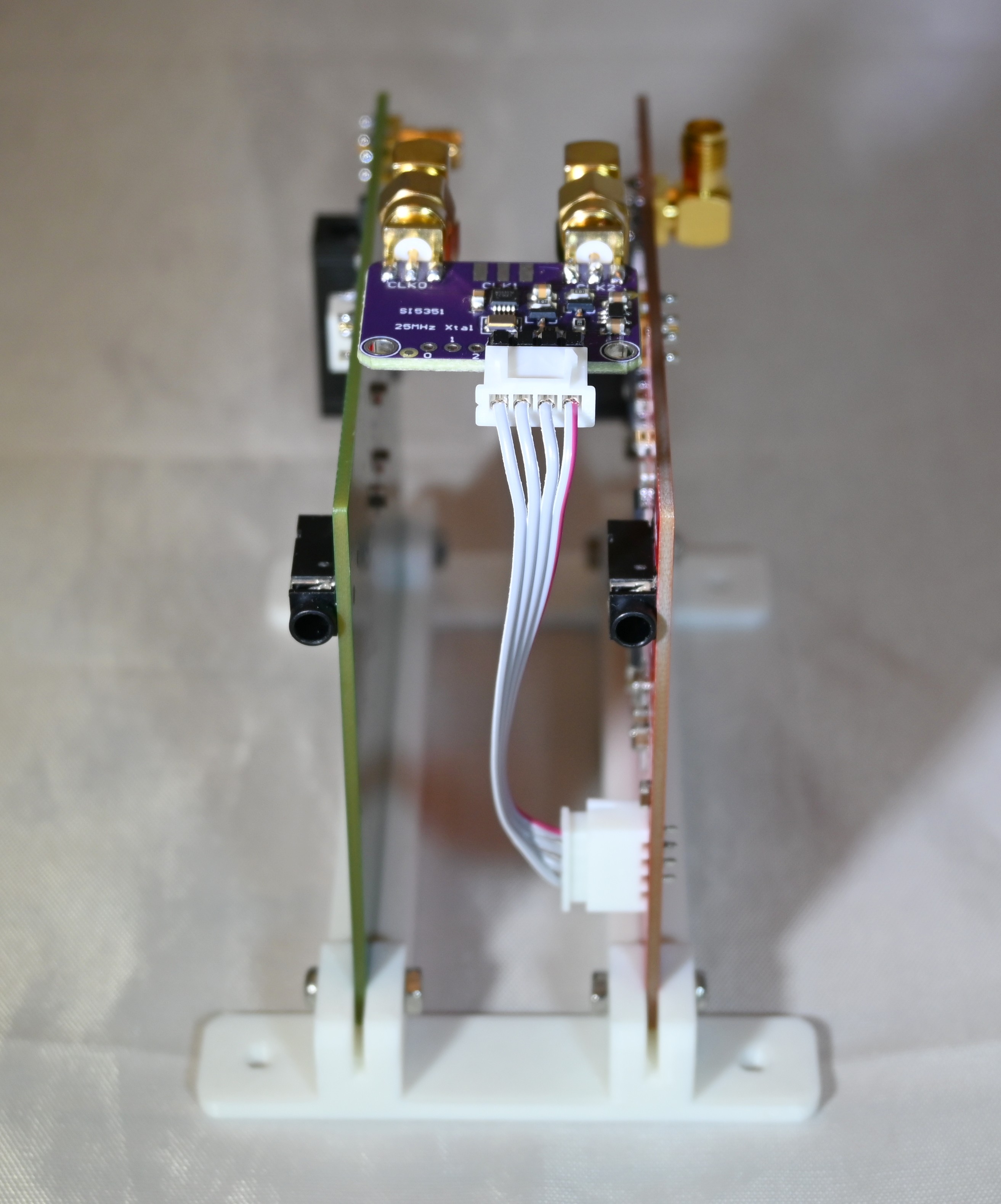
Note the cable from the Si5351 module to the QSE2. This 4-wire cable provides 5 volts, ground, and I2C data bus for the Si5351. Currently this is not used, as the V11 Main board does not include I2C output. What I am doing now is a hack of a couple of wires from the Main board for I2C and a couple more wires which tap 5 volts from the QSD2. The four wires hacked onto these boards are attached to a 4-pin connector, which slides onto the Si5351 module pins.
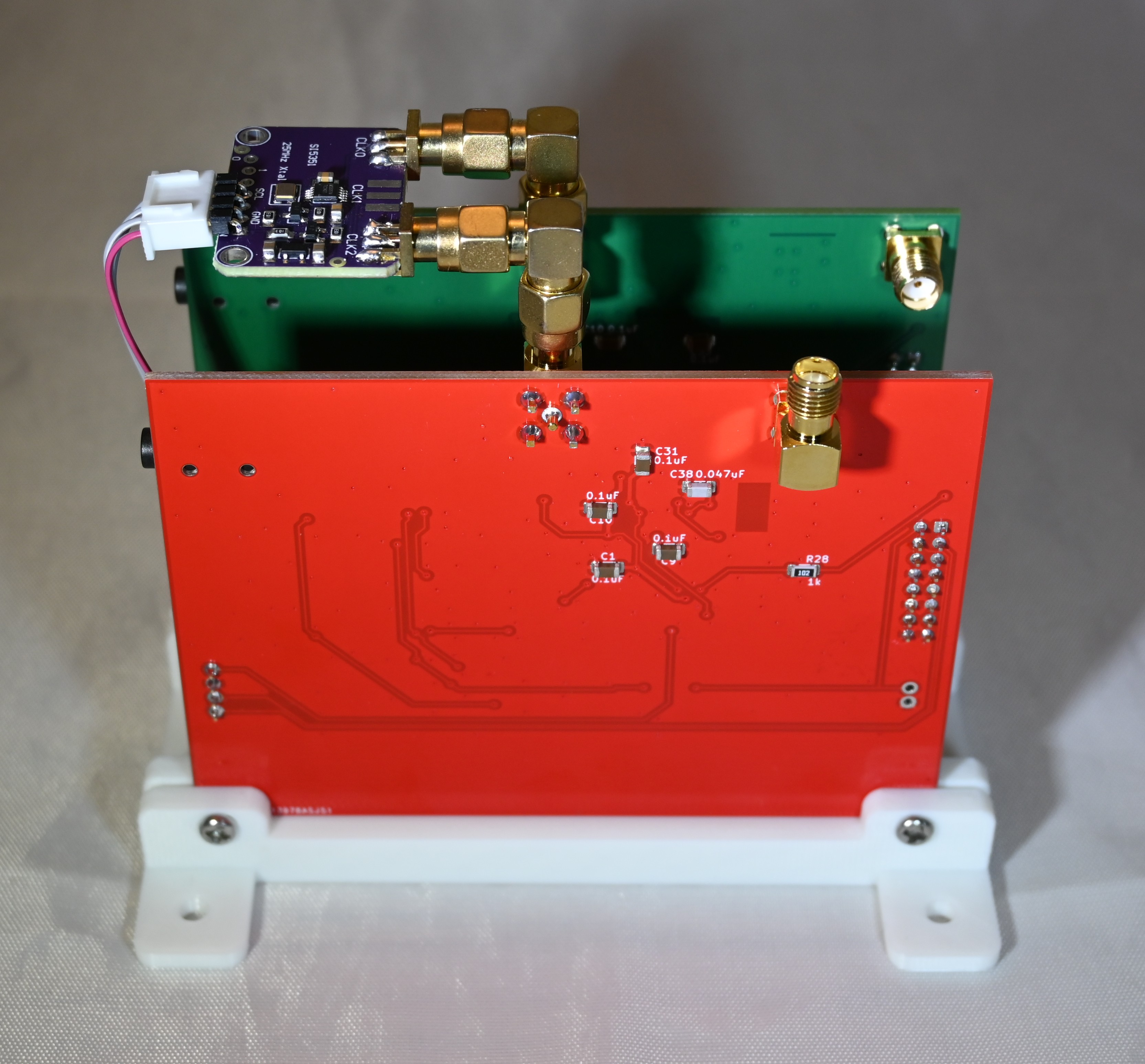
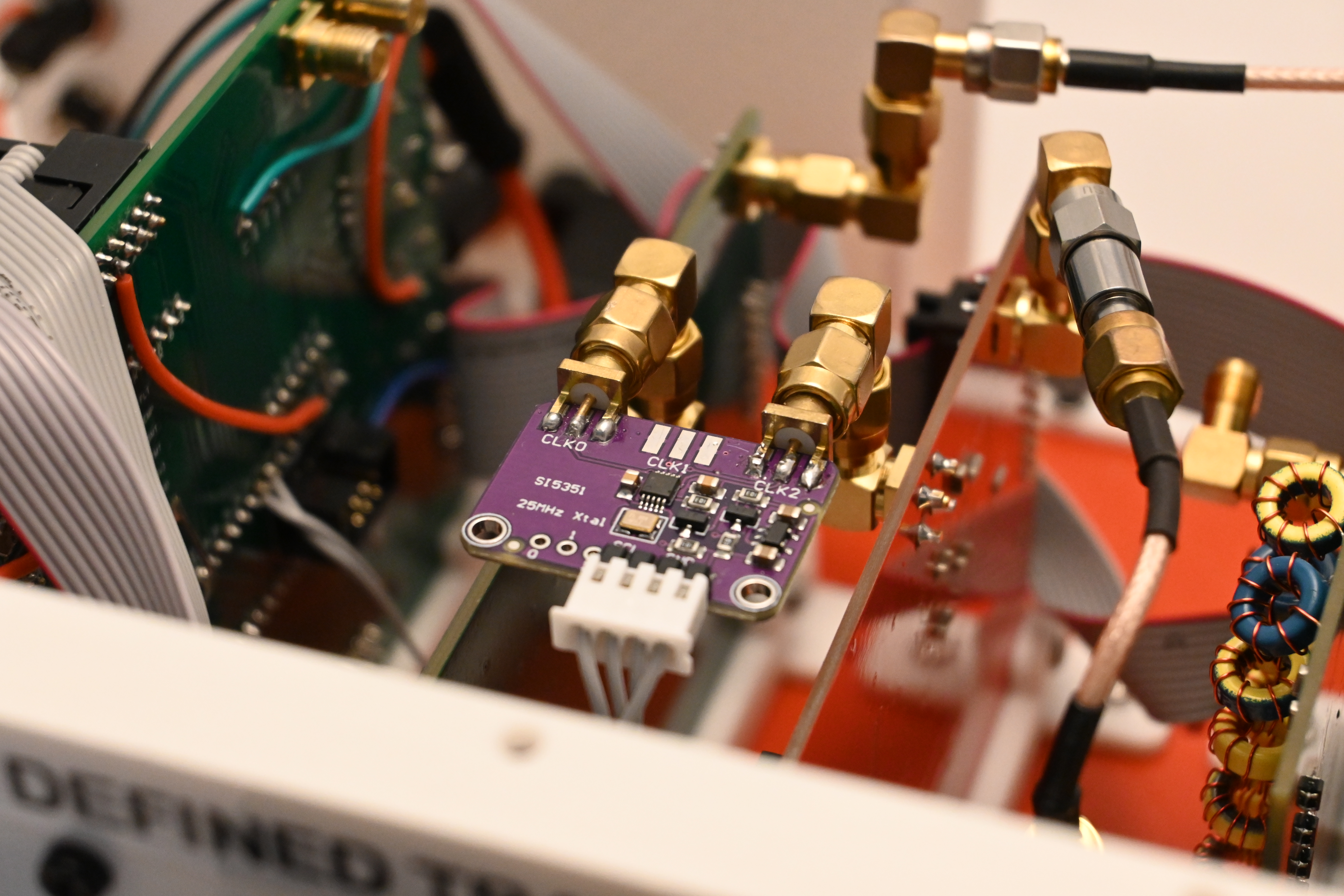
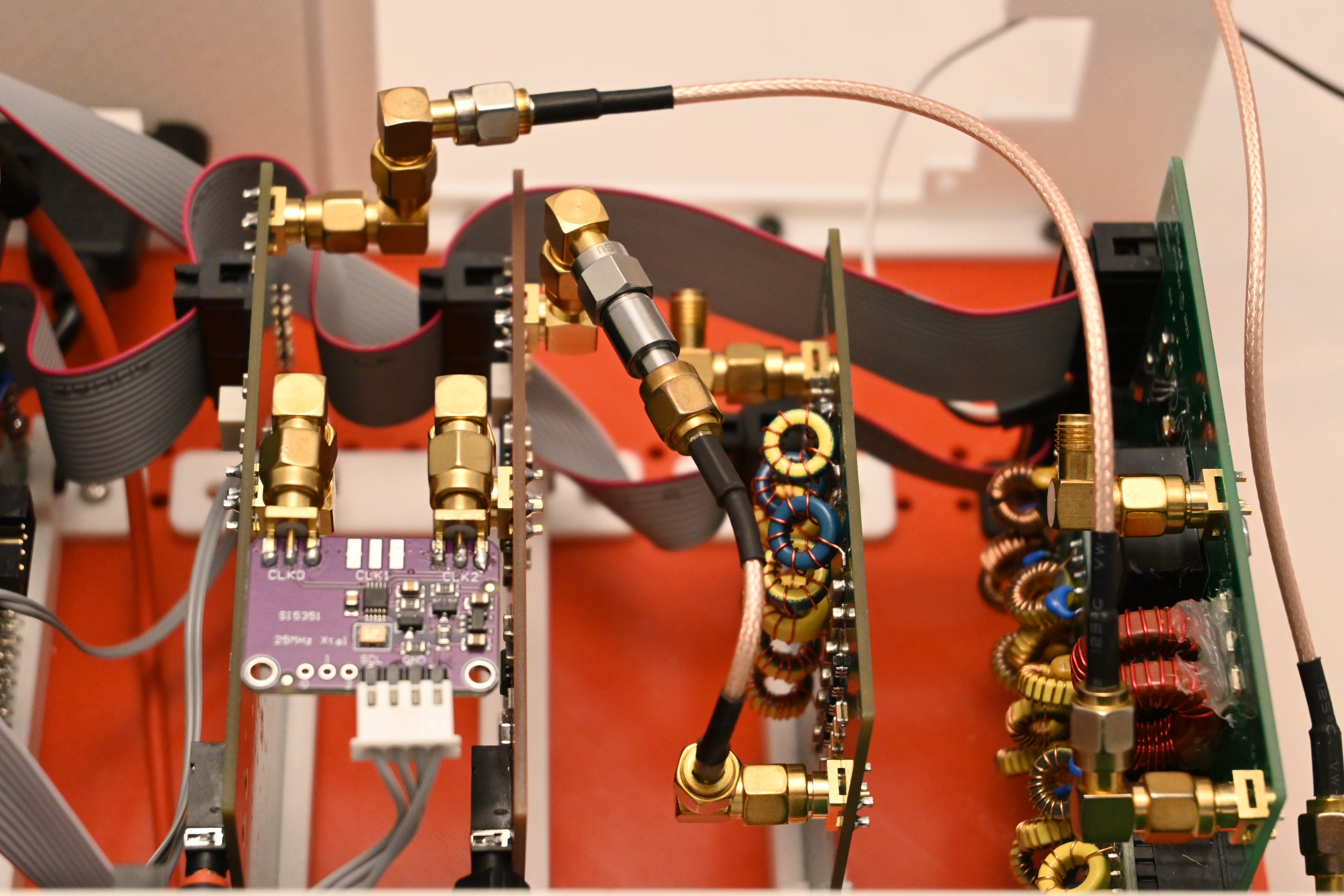
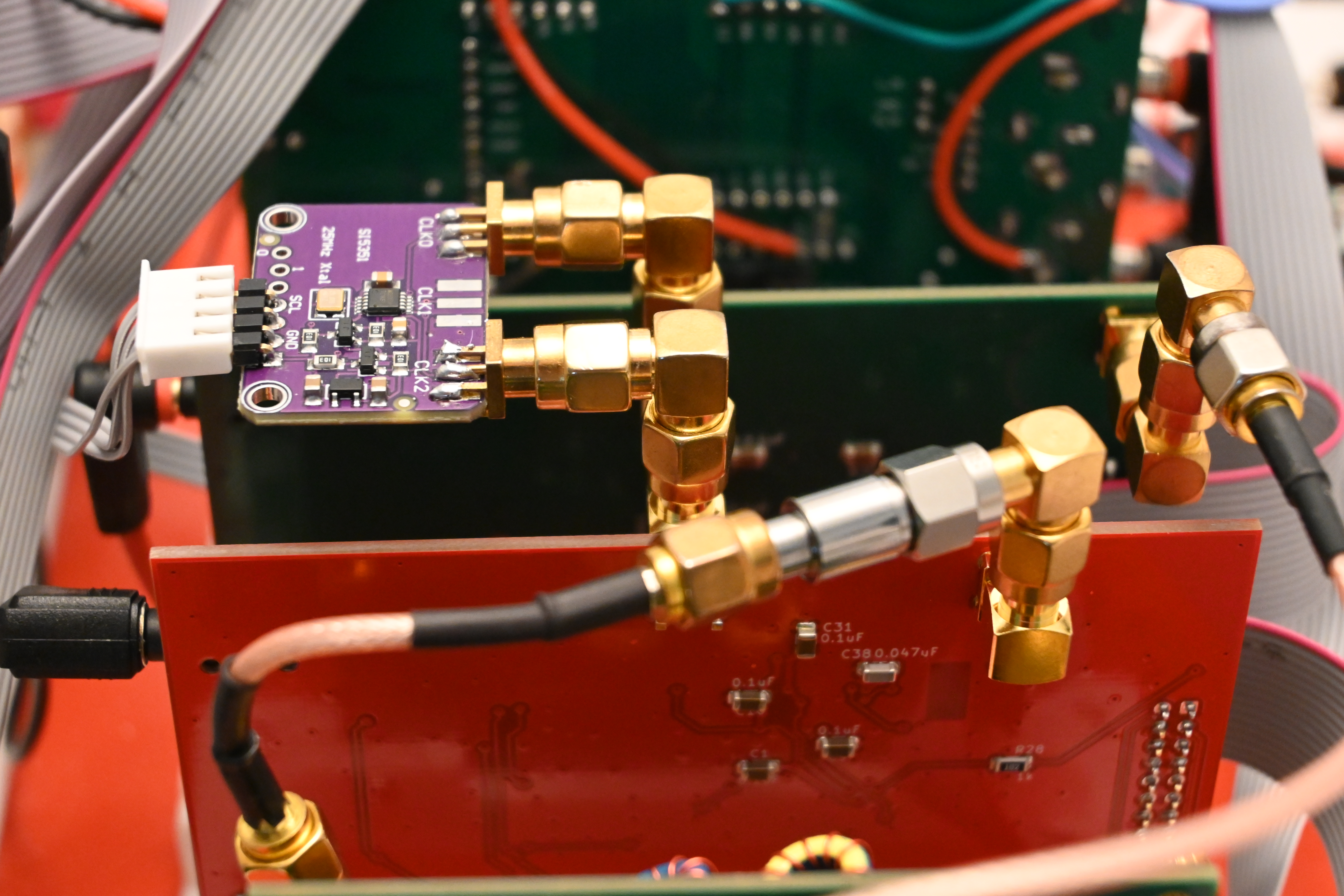
Here are photos showing the how the Si5351 module looks in the radio:
Cheap Si5351 Modules
Using an Si5351 module instead soldering it to the Main board solves several problems simultaneously. The Si5351 device is notoriously difficult to solder, as it uses very fine pitch leads. The small 25 MHz crystal is also difficult to properly solder, and it can be damaged by overheating. The module has these parts ready to go including regulators and decoupling. Even better, the RF connectors are included! Here is the module I used from Amazon:
https://www.amazon.com/gp/product/B09DM96KGS
Note that the two outer outputs are used, ClK0 and CLK2. The output in the center, CLK1, is not used.
I used these double-male 90 degree adapters for attaching the Si5351 module to the assembly:
https://www.amazon.com/gp/product/B07F9V9Q6V
Note that assembling in this way makes the Super-Module taller. However, if the CLK input connectors are rotated 90 degrees, it will be possible to use straight SMA male-male adapters and the total height will be very close to that of the QSE2 and QSD2 boards. The Si5351 module will be positioned between the top edges of the two boards.
Software Configuration for the QSD2/QSE2 Super-Module
The T41EEE firmware for the T41 transceiver can be configured for the QSD2/QSE2 Super-Module.
https://github.com/Greg-R/T41EEE
In the file MyConfigurationFile.h:
// Uncomment this line if using an external PLL module.
//#define PLLMODULE
All you have to do is uncomment one line:
// Uncomment this line if using an external PLL module.
#define PLLMODULE
This will cause the Si5351 module to be programmed to use the CLK0 and CLK2 outputs as required for transmit, receive, and calibration.