KF5N Radio Experimentation Site
Power Amplifier
T41-2 Power Amplifier Version 1.7
This is the PCB for the Power Amplifier for the T41 “Software Defined Transceiver”. This PCB was designed using the open-source design tool Kicad 9.0. The github repository is here:
https://github.com/Greg-R/t41_2_power_amplifier
The Power Amplifier is designed to driven by the T41-2 Low Power Amplifier, described here:
The Low Power Amplifier combined with the Power Amplifier are intended to replace the original V11 Power Amplifier which uses IRF510 switching MOSFETs in the final amplifier stage. This new design will improve all aspects of power amplifier performance, including linearity, power, efficiency, and bandwidth. An important difference is that the amplifier operates from a 13.8 volt supply. No “boost” module is required.
The schematic is here:
https://github.com/Greg-R/t41_2_power_amplifier/blob/main/doc/t41_2_power_amplifier.pdf
Licensing
Please note the included license files. The software license, GNU GENERAL PUBLIC LICENSE Version 3, covers the design files. The hardware license, CERN Open Hardware Licence Version 2 - Strongly Reciprocal, covers the PCB and circuitry.
Design Details
Amplifier Design Notes
The Power Amplifier is a conventional push-pull circuit using Mitsubishi RD16HHF1 devices.
The input network is an impedance matching transformer with a center-tapped secondary. A resistive network is used for DC gate bias of the MOSFETS as well as for stability. The two MOSFETs have independent bias adjustments due to the wide threshold voltage variation of MOSFET devices.
A bifilar wound inductor provides DC bias to the MOSFET drains.
Each MOSFET has a transformer wound on a binocular core. These are combined in parallel on the output. This results in a compact layout while preserving good bandwidth.
DC Biasing and Thermal Protection Circuits
A 10 volt regulator provides the bias voltage to the potentiometers which are used to set the MOSFET quiescent bias currents.
There is also an optional “thermostat” device which shuts down the amplifier if the temperature rises above a threshold set by a resistor value. The thermostat is positioned in close proximity to the output amplifier devices. Experiments are ongoing with this device to determine what temperature setting should be used.
Please note the electrolytic capacitors on the 13.8 volt supply net. These are not required in the case of a 13.8 volt supply voltage. The 10uF ceramic capacitors, rated at 25 volts, are used in this case. If it is desired to operate at a higher voltage, the ceramics must be replaced with higher voltage electrolytics (not tested yet).
Bill of Material
The Digikey BOM is here:
https://www.digikey.com/en/mylists/list/1GX6JR00JS
Four ferrite cores are required:
Quantity 2 BN-43-302 binocular cores. Quantity 2 BN-43-202 binocular cores.
You will also need a small quantity of #24, #26, and #22 magnet wire. I order this on spools from Amazon:
https://www.amazon.com/dp/B07DYF89T9?th=1
I ordered the cores from:
Also some hardware is required. I used this outstanding heatsink:
https://www.amazon.com/dp/B07TJY3GKP?th=1
Some sort of stand-offs or spacers are required to hold the PCB above the heatsink. These 5mm spacers are perfect:
https://www.amazon.com/dp/B0CQ3TKVBD?th=1
I use this type of caphead bolt to secure the PCB to the heatsink:
https://www.amazon.com/dp/B0DYMYHHWH?th=1
Two 3mm bolts and washers are required to bolt down the final amplifier devices. A small amount of heatsink compound under the devices is recommended.
A 5 amp bladed style automotive fuse is required.
The Mitsubishi RD16HHF1 RF power amplifiers devices will take some effort to locate and purchase. The problem is that there are counterfit devices for sale. It is absolutely essential to use genuine devices.
I have been successful using devices from this Aliexpress dealer:
https://www.aliexpress.us/item/2251832495725731.html
There is a particular shape of the device’s source terminal to look for which can indicate a genuine device or not.
Here is another source for genuine parts:
https://www.rfparts.com/rd16hhf1-501.html
Build Instructions
The Power Amplifier build is similar to the other boards in the T41-2 series, with the exception being the ferrite cores which must be constructed with great care. I am going to create another document to cover the construction of the three ferrite devices (T1, L2, T2 and T3).
The installation of the final amplifier devices Q1 and Q3 will be covered in the same document as the ferrites.
The board has components on both sides. I recommend using a hot plate for the top side components. Use a hot air gun for the bottom side components.
Tune Up
DC Bias Adjustment
There is an DC bias current adjustment for the two final amplifier MOSFETs. The potentiometers are R17 and R11.
It is important to set the potentiometers for minimal bias current before applying power!!! If the potentiometer is oriented as in the photograph (below) the potentiometer should be rotated counterclockwise until up against the stop. Make sure both are set against the stop before proceeding with bias adjustment.
Since this is a Class-AB amplifier, the bias point should be set for optimal linearity at the lowest current possible.
There is a trade-off here between linearity and efficiency. The recommended bias current was determined emperically. However, if you want more efficiency, and you are a CW operator only, decrease the bias current. If you want even more linearity for SSB operation, increase the bias current, with the trade-off being less amplifier efficiency.
The 13.8 volt current should be set for approximately 500 milliamperes per device with no RF drive. Slowly rotate one of the potentiometers clockwise until this current is achieved. The current may drift a few milliamperes as the devices warm up. This is normal, and the exact bias current setting is not critical. Continue with the second potentiometer until the total bias current is 1.0 amps.
Linearity Testing
The T41EEE firmware includes a “two-tone” test which can be used to evaluate the linearity of a power amplifier.
High Resolution Photos
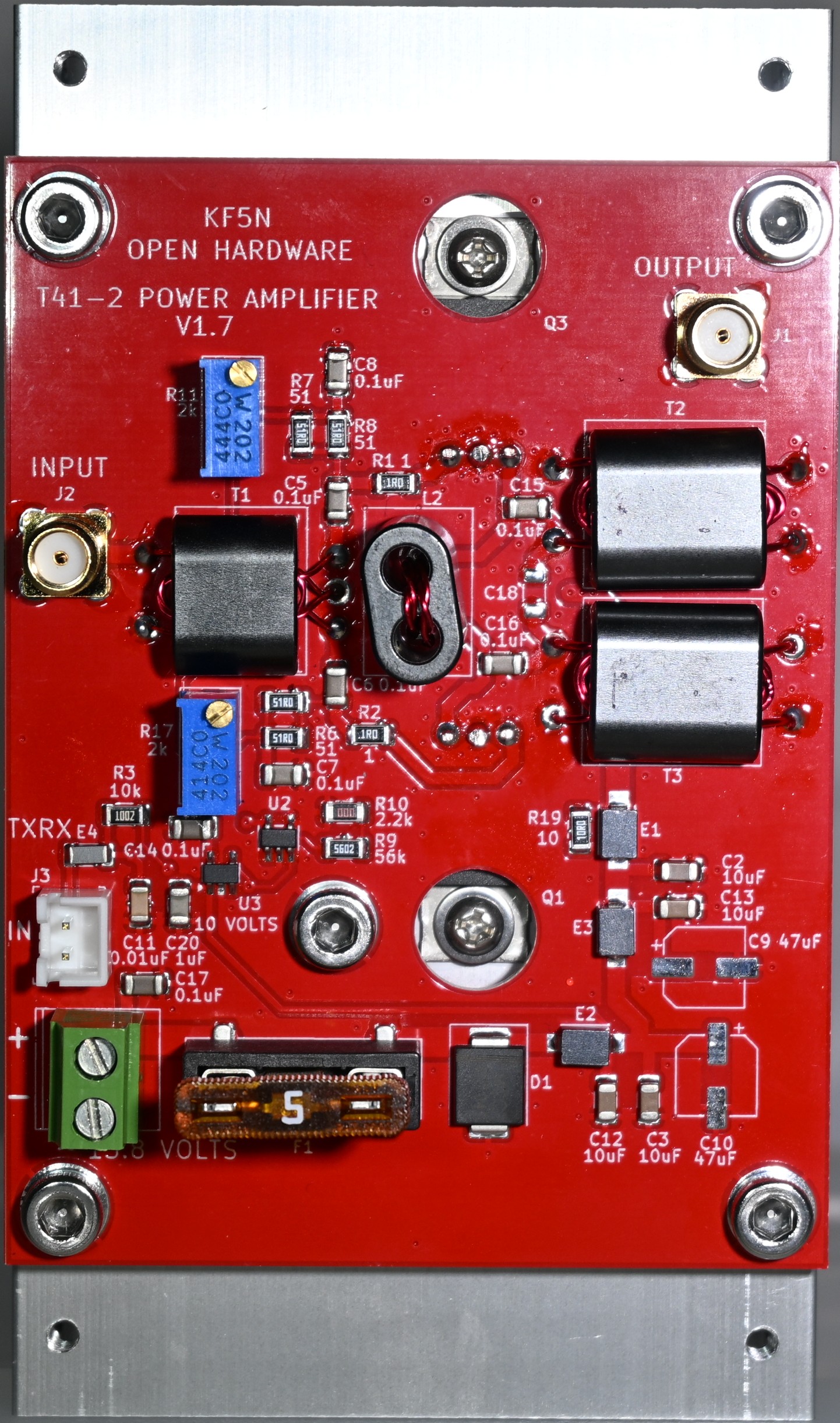
Click on the image for a downloadable high-resolution image. The front side of the completed board:
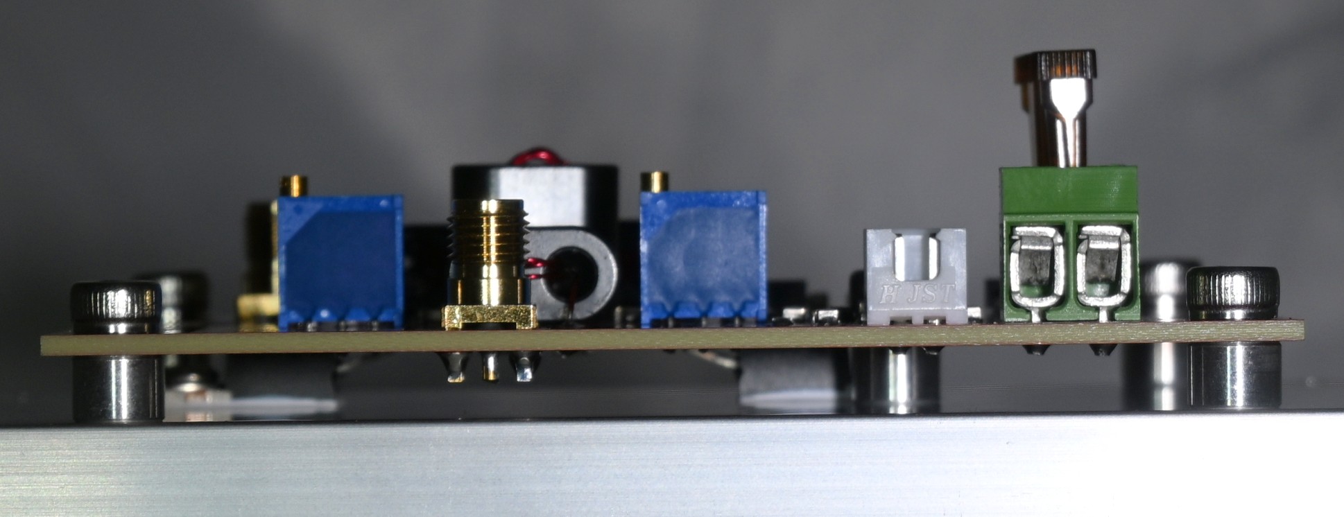
Side view of the completed module, showing the heatsink, TO-220 devices, and spacers:
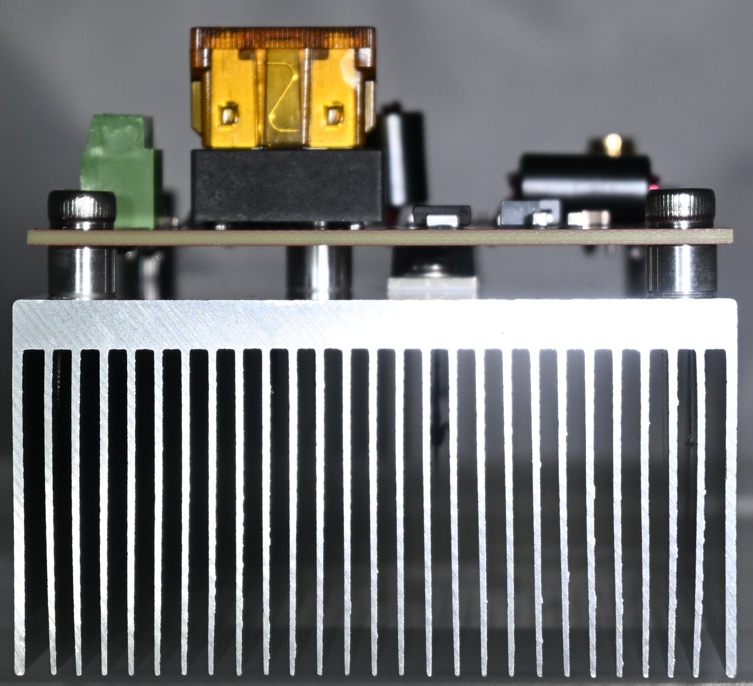
End view of the Power Amplifier, showing the spacers and heatsink:
Mounting the Power Amplifier to the T41 Radio
By drilling and tapping four holes in the extension of the heatsink, the Power Amplifier module can be mounted to the back side of the radio.
The FreeCad design file for a rear case panel is here:
https://github.com/Greg-R/SDT_Case_KF5N/tree/main/case
There are a lot of files in that folder. The revised rear panel is:
Rear_Full_panel_2025_KF5N_2.FCStd