KF5N Radio Experimentation Site
Low Power Amplifier
T41-2 Low Power Amplifier Version 1.6
This is the PCB for the Low Power Amplifier for the T41 “Software Defined Transceiver”. This PCB was designed using the open-source design tool Kicad 9.0. The Github repository is here:
https://github.com/Greg-R/t41_2_low_power_amplifier
The Low Power Amplifier is designed to drive the T41-2 Power Amplifier, described here:
The Low Power Amplifier combined with the Power Amplifier are intended to replace the original V11 Power Amplifier which uses IRF510 switching MOSFETs in the final amplifier stage. This new design will improve all aspects of power amplifier performance, including linearity, power, efficiency, and bandwidth. An important difference is that the amplifier operates from a 13.8 volt supply. No “boost” module is required.
The schematic is here:
https://github.com/Greg-R/t41_2_low_power_amplifier/blob/main/doc/t41_2_low_power_amplifier.pdf
Licensing
Please note the included license files. The software license, GNU GENERAL PUBLIC LICENSE Version 3, covers the design files. The hardware license, CERN Open Hardware Licence Version 2 - Strongly Reciprocal, covers the PCB and circuitry.
Design Details
First Amplifier Stage
As the T41 is an “Experimenter’s Platform”, the Low Power Amplifier includes circuits which are intended to test ideas which could possibly be used in other applications.
The input includes a pi resistive attenuator. The schematic shows fixed values, but these can be altered to match a particular application. The values shown are intended to work with the output level of the QSE, which is about -10dBm. Note that the second shunt resistor is “DNP” (Do Not Place), as the input of the amplifier provides the required shunt impedance.
The first stage, which is actually a two-stage amplifier, is a discrete implementation of a “Darlington” style RF amplifier. This is an experiment I have wanted to try for quite a while. Darlington RF amplifiers are available in numerous configurations as integrated circuits, however, I wanted to see if a wideband Darlington could be made to work with discrete NPN transistors. After numerous experiments, it was decided to use the BRF106 BJT device in the circuit. The feedback values were adjusted to achieve desired impedance and gain levels.
It did not appear to be a good idea to run the Darlington amplifier from the 13.8 volt supply. It is important to keep the voltages and currents stable, which in turn keeps impedances and gains constant. This means a voltage regulator had to be added to the circuit. A SOT-23-5 package 10 volt regulator was found which works perfectly. This regulator has the benefit of a shutdown pin. The shutdown pin is connected to the TXRX signal.
Second Amplifier Stage
In order to drive the Power Amplifier, the second stage of the Low Power Amplifier needs something on the order of a quarter to half watt output power with good linearity. Strangely enough, this is something which may be more difficult to achieve than it was in the past. At least with discrete components, which was a primary goal of this design.
Back in the “good old days” there were devices like the 2N4427, 2N3866, and 2N5109 in the sturdy metal TO-5 package:
https://en.wikipedia.org/wiki/TO-5
Now I could probably find a cache of the old TO-5 parts, but what I wanted was the “modern” version of these devices. That turned out to be a difficult search! This is what seemed to be the 21st century RF low-power device:
https://www.nxp.com/part/BFU590G#/
But even this device has a last-time buy date of June 2026! Fortunately they are still in stock at the usual distributors. In quantities of 10, they cost US$0.77, so quite a bargain for a 8.5GHz RF device.
After a bit of simulation, the chosen amplifier circuit is simple. By using series and shunt feedback the amplifier has good linearity and power.
Next, putting the gain stage into a push-pull configuration was required to maximize power and cancel even harmonics. A simple class-AB bias circuit uses another RF transistor, the BRF92, to stabilize the DC bias current.
A second 10 volt regulator is used to bias the output stage. This regulator has output current limiting (about 200mA) and thermal shutdown. The SOT-89-5 package can dissipate quite a lot of power, thanks to the large ground tab.
There is also an optional “thermostat” device which shuts down the amplifier if the temperature rises above a threshold set by a resistor value. The thermostat is positioned in close proximity to the output amplifier devices. Experiments are ongoing with this device to determine what temperature setting should be used and if it is even necessary at all.
Bill of Material
The Digikey BOM is here:
https://www.digikey.com/en/mylists/list/TNVL59LTTS
Three ferrite cores are required:
Quantity 2 BN-43-302 binocular cores. Quantity 1 FT37-43 toroid.
I ordered the cores from:
You will also need a small quantity of #26 and #288888888 magnet wire. I order this on spools from Amazon:
https://www.amazon.com/dp/B07DYF89T9?th=1
Build Instructions
The Low Power Amplifier build is similar to the other boards in the T41-2 series, with the exception being the ferrite cores which must be constructed with great care. I am going to create another document to cover the construction of the three ferrite devices (T1, T3, and L1).
The board has components on both sides. I recommend using a hot plate for the top side components. Use a hot air gun for the bottom side components.
Tune Up
DC Bias Adjustment
There is only a single adjustment and that is via the multi-turn potentiometer R17.
It is important to set this potentiometer for minimal bias current before applying power!!! If the potentiometer is oriented as in the photograph (below) the potentiometer should be rotated counterclockwise until up against the stop.
Since this is a Class-AB amplifier, the bias point should be set for optimal linearity at the lowest current possible.
I found the optimal bias current while driving the Power Amplifier module and monitoring for best linearity during a two-tone test.
The 13.8 volt current should be set for approximately 150 milliamperes with no RF drive. Slowly rotate the potentiometer clockwise until this current is achieved. The current may drift a few milliamperes as the devices warm up. This is normal, and the exact bias current setting is not critical.
Linearity Testing
The T41EEE firmware includes a “two-tone” test which can be used to evaluate the linearity of a power amplifier.
High Resolution Photos
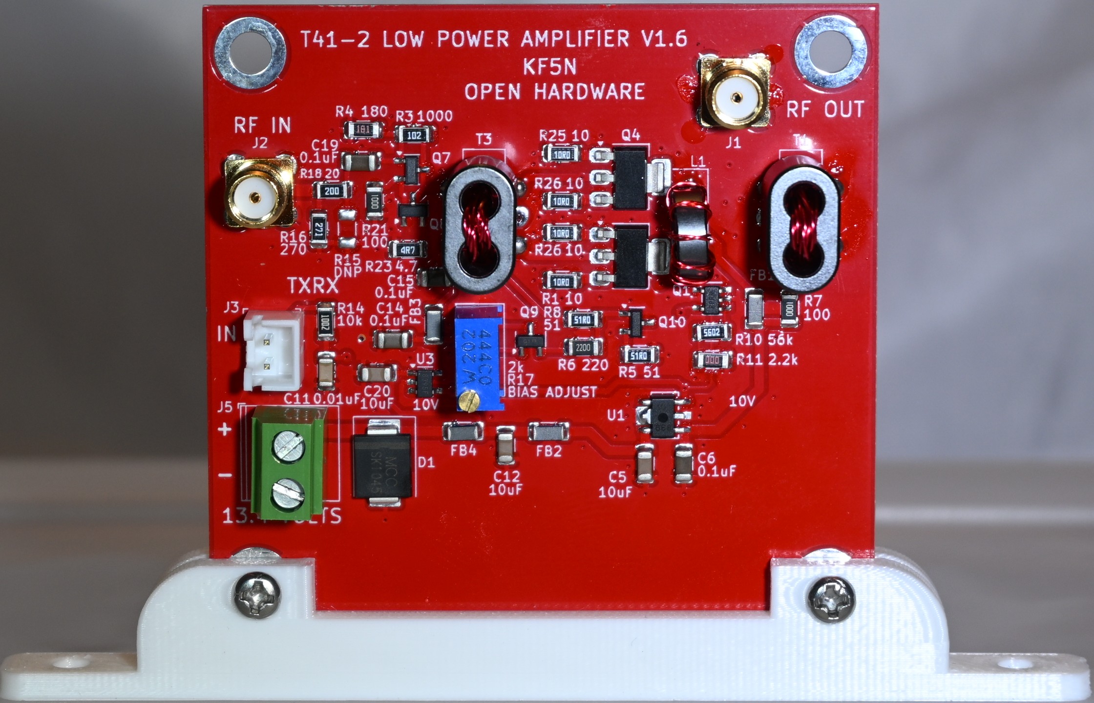
Click on the image for a high-resolution downloadable file. The top side of the completed board:
The bottom side of the completed board:
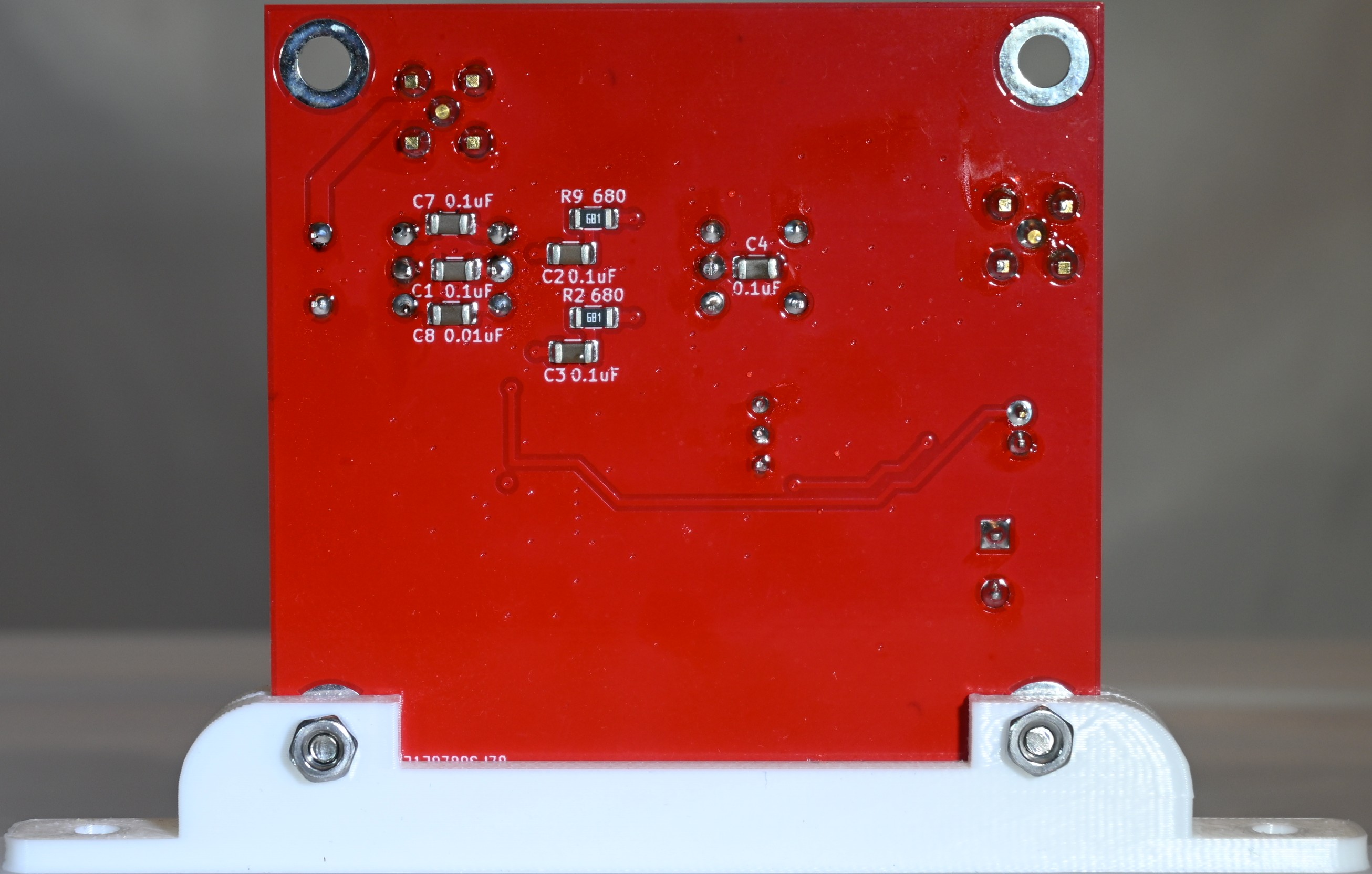
Please note a silkscreen error in the above image. The capacitance values of C1 and C8 are erroneously swapped.
Here are the erroneous and the corrected values:
- C1 0.1uF. This capacitor should be 0.01uF.
- C8 0.01uF. This capacitor should be 0.1uF.
The silkscreen has been corrected in the files in the repository. This error did not warrant an up-rev of the board.
Mounting Bracket
The FreeCad design file for a Low Power Amplifier mounting bracket is here:
https://github.com/Greg-R/SDT_Case_KF5N/tree/main/bracket
There is a standard four hole bracket, and a thin bracket with two mounting holes. The Low Power Amplifier is small and the thin bracket will probably be adequate, and it takes up less space on the chassis.